Factory Battery Tester
Among the seldom-seen optional accessories is the factory Battery Tester. This unit looks like the single-unit drop-in charger but with a analog meter (0 to 17 volts). Motorola anticipated a customer could have both high and low power versions of the "Omni" HT220, and provided the appropriate slot and a resistive "load" selected by the "hi" or "lo" button, representing the current drawn by the 1.8 watt or 5 watt transmitters. The tester thus minimized the need to have the actual radio in the test slot, since the battery itself could be dropped in, just as with the charging units. It also came with external DC test jack terminals.
Motorola's shift toward PLL and microprocessor-based portables caused some dissent among potential and subsequent customers because of the noticeably higher current draw and shorter battery life compared with the HT220. Indeed, with the advent of the modular MT500 and early complaints about how piggy the radios were with batteries, the company's National Sales department was reportedly told to stress the "energy saving" nature of the successor "MX" series radios, which ran on a 7.5 volt operating voltage, compared to the 15 volt operating voltage of the old HT220 (and MT500). What was intended to be left out of such a pre-emptive discussion is that the overall power consumption remained higher on the new radio (simple Ohm's law). Even with the latest energy-saving circuits which cycle a receiver's circuit on and off until a desired signal comes in, the HT220 receiver remains one of the most energy conservative hand-helds ever made.
Some Rare Options
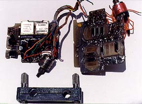
On the left upper is Motorola's rare dual PL encoder-decoder board for the HT220, allowing different transmit and receive tones. This board mounts in the extended" sleeve area of an "Omni" thickness radio and can also be installed in what started out as a "carrier length" Omni HT220.
The standard "Vibrasponder" unit is twice the size of these miniature versions, and takes up nearly all the space in the PL-area of a standard configuration radio. Usually the on-off PL switch on the top panel of the radio selects only whether the receiver is carrier- or tone-squelch. The transmit audio always includes the subaudible tone. It would be left to the experimenter to devise a way to affect the transmitted tone, or to configure the receive PL switch to select between the two Vibrasponder tones available with this module.
On the upper right is the six-channel board. Although this is a standard Motorola board, it seldom was used in what Motorola considered a full channel "Omni" configuration radio because it precludes the use of the popular 5-watt amplifier module. The amp sits in half of the extended sleeve area, and this board would take up more than half the space. It was generally used with the low power (1.8 watt) model, retaining an ease of crystal tune-up to the desired frequency.
For high powered models, Motorola (at the factory) or the savvy outside bench technician retrofitting such a radio would use the two channels (four crystal locations) available on the motherboard, and acquire a four-channel Motorola board (not shown). The six-position channel selection switch never knew the difference and the markings on the top plate and knob matched the radio's abilities. Configured this way, it was difficult to adjust the motherboard crystals since the tuning is somewhat dependent on having the entire radio compressed as if it were in use (see tuneup aid that follows). The factory did not offer an eight-position switch for those who preferred channel capacity over other options, but some hams accomplished that by directly buying such a switch from Grayhill, the subcontractor.
Tuning Aid
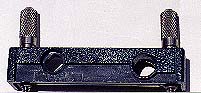
The unit on the right is one of two factory tuning aids designed to compress the radio's front plastic and metal chassis, while also connecting the RF tab on the motherboard to a threaded RF output. The second aid (not shown) covers the very top of where the back cover would normally go on either the Slimline or the Omni. The compression afforded by these aids replicates an assembled radio. Frequency tuning of the crystals is affected by the tightness of the case screws, and there is a Motorola torque specification applicable to both the assembled case and the use of these aids.
Board types to look for
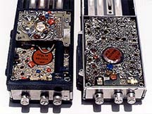
The oldest examples of the HT220 had problems with printed circuit foil lifting from the insulating material of the motherboard. This generally happened when the radio was repaired or when crystals were changed. Original, unmodified radios are difficult to find on the used market in the 30 years since they were manufactured, but Motorola did change the type of insulating board material in an effort to respond to the problem. Consequently, the interested buyer would do well to seek out the tan board seen on the left in the image, and check carefully before considering the green board on the right. There was a lot of mixing-and-matching among boards and subassemblies, making it difficult to conclude which motherboard is inside from any external cues. Shown on the left is a two-channel, carrier-squelch "E" board front housing (the only one with an earphone jack on the front edge), an "E" board tan motherboard, the "Omni" extension sleeve, and an older green board 5 watt amplifier module. On the right is an early, two-channel, carrier-squelch slimline with green board, revealing the RF tab in the lower right of the motherboard to which the test aid or back cover connects with the threaded antenna mount.